
Orientation and Geodetic Data

What is geodetic data? Microsoft’s SQL Server stores spatial data. Data is stored in two ways: geometry and geography, also known as planar and geodetic spatial types respectively. In other words, planar type is where data makes sense in theory, like on a perfectly flat graph paper, whereas geodetic type is where data makes sense in real life. This is also known as geodetic data, which includes geodetic location or geodetic position. In this spatial type, SQL Server does all the calculations assuming a round earth as compared to a cartesian plane.
It is very common for spatial data to be stored in geodetic coordinates, otherwise known as geodetic location or position. This type of spatial data includes latitude, longitude, and perhaps some kind of height. Some software can interpret this data geodetically. This takes advantage of a model of the earth’s shape to correctly answer questions like, “what is the distance between two points as the crow (or airplane) flies?”. Short of this ability to directly manipulate geometry on the globe, the next best option is to project the data onto a plane that minimizes distortion for a limited region. From here, you can analyze or manipulate the data in that context.
Orientation and Geodetic Data in Action
What natural ambiguity arises when reasoning about areas geodetically? Does that circle represent the small area inside or the large area outside if you draw a circle on the globe? Similarly, if you draw a circle around the globe at some latitude, does that represent the area above or below that circle? Some, but not all, geodetic-savvy spatial databases use orientation to make this distinction.
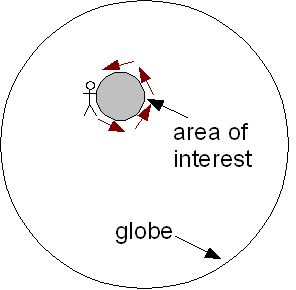
Figure 1: Example of the left-hand rule for geodetic data. A person walks around the outside perimeter with their left hand touching the boundary. If there are holes, the person walks around them from the inside, giving them opposite orientation.
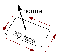
Figure 2: Contrast the right-hand rule often used with 3D data where you curl your fingers in the direction of the polygon vertices and your thumb shows which side is “up”.
This brings us to an interesting problem. What if we want to load data that doesn’t already follow these orientation conventions? This is because this situation is inherently ambiguous. You have to choose the polygon orientation that encloses the smaller area, i.e. the geometry in question and not the rest of the world. Jason Follas discussed this challenge in the context of loading geodetic data into SQL Server.
Pitfalls of Not Considering the Earth’s Shape
I’d like to discuss an interesting pitfall of using the following algorithm:
Take your lat/long data. Pretend it is on a plane (the “plate carrée” projection), and use a non-geodetic algorithm to fix the ring orientations. This is the strategy FME uses currently. Ed Katibah demonstrates how to do the same thing inside SQL Server in an earlier blog post.
Case Studies
This algorithm breaks down in three cases:
1) Geometries that cross the 180 degree meridian. This is the most common trouble and the easiest to work around. This comes in two variants. In the first case, the offending geometry is broken into an aggregate of two pieces: the part east of the meridian (>= -180 longitude) and the part west of the meridian (<= +180 longitude).
The trouble with this data is that SQL Server doesn’t like aggregates of areas that share a common edge. In the second case, the offending geometry is all in one piece, but adjacent vertices jump between longitude values just east of -180 and just west of +180. Often, this can be worked-around by adding 360 to all of the negative longitudes.
2) Geometries that enclose a pole. As before, these come in two variants: either the data has been formatted for viewing in two dimensions, with a line from (-180,+-90) to (+180,+-90), or it has not.
In the first case, there will be a common edge or sliver at the +-180 degree meridian, and orientation must be handled specially. In the second case, it is not easy to determine that a pole has been enclosed, orientation is ambiguous, and the data may appear to self-intersect.
3) Extremely large, narrow polygons. This is the most interesting (and rare) case. It turns out that a polygon can have one orientation when we pretend the lat/long data is planar and another orientation when we treat it geodetically.
Imagine a flight from Vancouver (Canada), to Edmonton, to Amsterdam, and then back to Vancouver. When viewed in plate carrée, this path looks clockwise. However, when viewed on the globe, the path looks counterclockwise because the flight from Amsterdam to Vancouver is much further north than the path from Vancouver to Edmonton. This situation can also occur for polygons that enclose a small area, as long as they are sufficiently narrow.
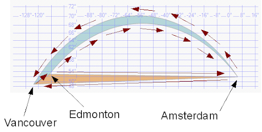
Figure 3: Viewed geodetically, the path is counterclockwise (blue). Viewed on a plane, the path is clockwise (orange).
As alluded to above, an alternative approach that works in many of these cases is to reproject each feature to an appropriate local coordinate system before determining whether or not orientation changes are required. We commonly use similar strategies when solving problems that mix geodetic and planar data, e.g. “starting with airport locations in lat/long, buffer them all by 10 km, and output the result in lat/long.”
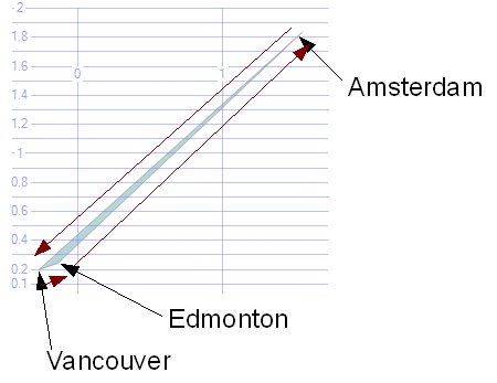
Figure 4: The same path viewed in the north-pole gnomonic projection. (The gnomonic projection has the interesting property that a straight line drawn between any two points traces the shortest path between those points on the globe.) The polygon is counterclockwise, as in the geodetic case. For smaller features, you might use a dynamically generated coordinate system centered on the feature in question instead.
As you’ve seen, there are some limitations to simpler alternatives to solving this orientation problem. The fact that small polygons far from the 180 meridian and poles might reverse orientation when approximating geodetic data as planar was particularly interesting to me. So when it comes to loading data into SQL Server, the best compatibility is achieved by using their algorithm which computes orientation geodetically.
FME & computing orientation geodetically through workflows
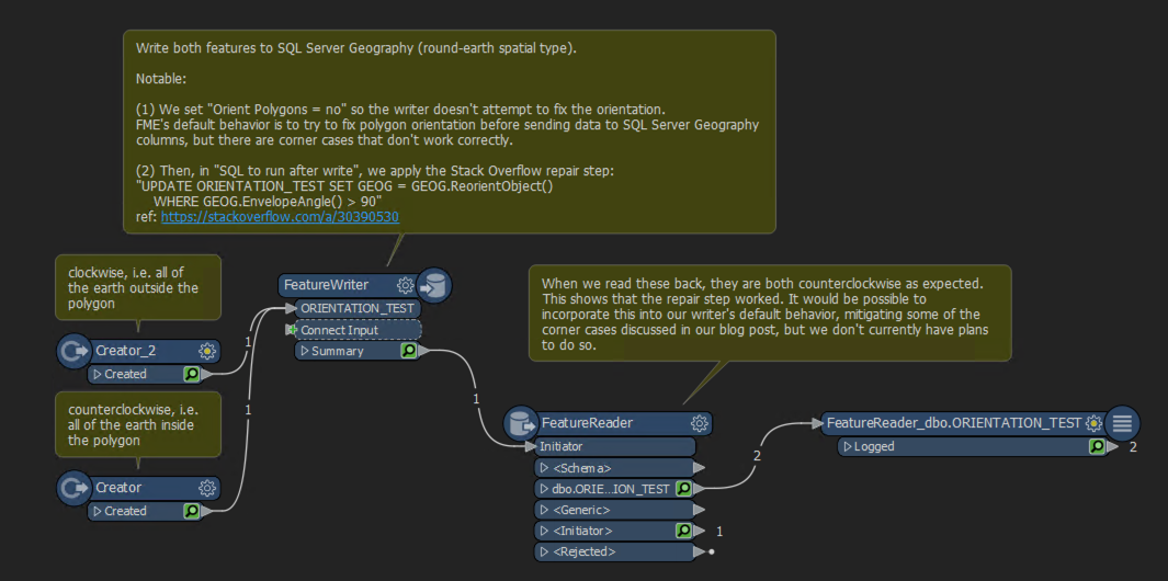
So when it comes to loading data into SQL Server, here is our effective solution for the best compatibility: let SQL Server answer the orientation question itself. Based on this Stack Overflow answer, you can also see how this workspace computes orientation geodetically. It finds all the geography values in a table that cover more than a single hemisphere, and inverts them.
Explore more blog content headline

Data-Driven Marine Operations: 5 Ways to Generate Actionable Insights from Ship to Shore


Introducing FME Form 24.0: Redesigned User Experience for Focus and Consistency


[New!] AI Assist in FME: How to Build Better Data Integration Workflows with the Help of AI