Converting GIS features to CAD drawings is notoriously difficult, but in a world where data needs to be interoperable between systems and formats, this task is often unavoidable. We see this workflow all the time for data technicians who need to create alignment sheets and as-built drawings — both to accept data from clients and to collaborate across teams.
A lot of tools can do a quick conversion between these data types. But maintaining data quality is the challenge. When you convert GIS data structures to CAD drawings, you need to:
- Convert GIS points into CAD cells or blocks.
- Convert GIS attributes into CAD annotations, labels, and symbology.
- Generate important CAD elements like tags, extended entity data, and object data.
- Reproject to a local coordinate system like WCS.
Here’s how to overcome these top GIS-CAD conversion challenges.
See also: Converting CAD to GIS
How to Convert GIS to CAD
In FME, your workflow has three parts: a Reader extracts the data from its GIS source (e.g. Shapefile, Geodatabase, Oracle, SQL Server, MapInfo, PostGIS, GML, etc.), transformers process and style the data, and a Writer sends the data to your CAD output format of choice (e.g. AutoCAD or MicroStation). FME workflows are repeatable and can be run on demand, on a schedule, or in response to an event (like when a client submits new data).
FME does most of the GIS-CAD conversion automatically, but the “transformation” part is where you can customize how you want FME to handle the details.
Here is a general MapInfo to Microstation tutorial to guide you through a conversion. The same principles apply to other GIS and CAD formats. Let’s look at some of the details of GIS-CAD translations more closely.
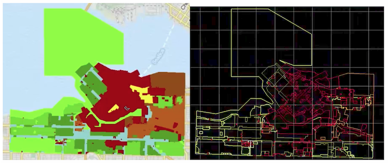
An example GIS to CAD conversion seen in this MapInfo to Microstation tutorial
Symbology
Add a DWGStyler or DGNStyler transformer to your workflow to style the data features. You can also create a CAD template file to define the header of layers, layer colors, and block definitions. This DWGStyler tutorial has some helpful guidance on template files, blocks, and more.
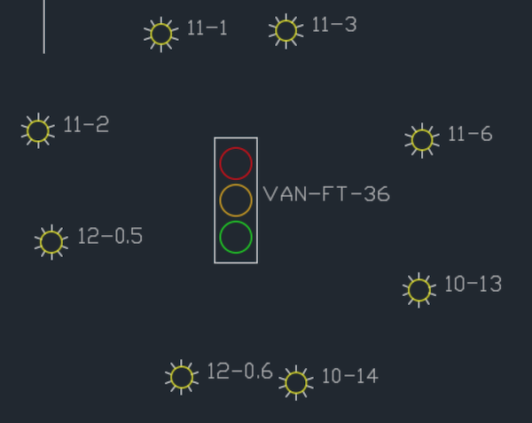
The DWGStyler and DGNStyler transformers enable you to do advanced styling on your output CAD drawing.
Try this example FME template that converts a GIS dataset to CAD. The data is symbolized depending on whether the features are areas, points, lines, or text. You can play with the template to adjust it to your own data.
Annotations and labels
FME will often convert text data automatically, but some GIS formats, like Geodatabase, don’t contain annotations. To convert GIS attributes to CAD annotations, you’ll want to use the Labeller transformer or the DWGStyler to set text properties on your CAD output. Another useful transformer is the LabelPointReplacer, which replaces each point or line with a text feature based on a GIS attribute value (prefix this with the CenterPointReplacer to replace each polygon with a point).
Coordinate systems and spatial accuracy
GIS, being designed for mapping data, is often represented at a larger scale than CAD data, which means this conversion often requires a reprojection. Use the Reprojector transformer to convert the global GIS coordinate system to a local one, like WCS.
Geometry
Styling geometry during your conversion workflow will allow you to manage how you want the geometry to be represented in the output CAD file. FME has an entire category of transformers dedicated to geometry operations, like dissolving boundaries, extruding to 3D, snapping nearby geometries together, and much more.
This geometry conversion tutorial demonstrates how to convert and style polygons and lines, as well as how to create text features from GIS attributes and write them as DGN text levels.
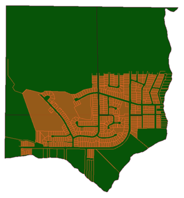
The result of converting Geodatabase to Microstation DGN using FME.
If you have polygons with holes, say, a Shapefile with buildings cut out of large areas, FME is good at handling these “donuts”. Use the DWGStyler or DGNStyler to convert the polygons to MPolygon or Hatch to retain the outer shell-hole relationship.
When converting points to cells, you can set the size of each cell based on the value of a GIS attribute. This Getting Started with AutoCAD tutorial will guide you through working with blocks and other AutoCAD essentials.
Data validation
FME also has an entire category of transformers for validating the quality of your data. This is an important final step in your workflow before you send the data to the destination CAD file. Add transformers to check the geometry for problems like self-intersections and null values, verify the data complies with standards, remove duplicates, and filter the results. You can also generate a validation report and email this to stakeholders.
Automation & self-serve data submissions
Running your GIS-CAD workflows in an event-based environment is the next step to making this task fully automated. In FME Server, set up an Automation to trigger your workflow on a schedule, whenever new data arrives, or in response to a number of other events.
To enable clients and stakeholders to submit data and have it converted or validated automatically, you can create a data portal. Try this example self-serve CAD validation portal.
Learn more about automating your GIS-CAD workflows using FME Server.
Case Study: “CAD/GIS Cartography” for Alignment Sheet Production
Global Information Systems provides the pipeline industry with solutions to manage asset data, business workflows, and regulatory compliance. In this industry, alignment sheets are critical for designing, maintaining, and communicating information about pipelines, as they show the route, location, and all information about a pipeline and related facilities.
Using FME, they created a system that automates alignment sheet production. Their FME Workspace converts Geodatabase to AutoCAD and makes use of several transformers for data manipulation and formatting. This system saves them time and money while allowing them to leverage both CAD and GIS software.
Watch Global Information Systems’ FME UC 2014 presentation to learn more.
Having an automated workflow that effortlessly converts GIS to CAD will allow everyone to keep using the best application for their job. Clients and colleagues can send you their Shapefiles and Geodatabases, and you can rest assured knowing you’ll be able to make use of this information in your everyday AutoCAD environment.
What are you working on that requires you to convert GIS to CAD? Do you have challenges beyond what was covered in the list above? Let us know!
In addition, join us in our upcoming webinar, How to Automate CAD & GIS Integration, on May 13 to explore the power of automated data integration workflows for CAD and GIS.
Related webinars:
- 5 Tips for Integrating CAD Data with Esri ArcGIS
- How to Exchange Data between CAD and GIS
- How to Transform Data between AutoCAD and GIS
- MicroStation DGN: How to Integrate CAD and GIS
- 3 Tips for Total CAD-GIS Integration

Tiana Warner
Tiana is a Senior Marketing Specialist at Safe Software. Her background in computer programming and creative hobbies led her to be one of the main producers of creative content for Safe Software. Tiana spends her free time writing fantasy novels, riding her horse, and exploring nature with her rescue pup, Joey.